11 Common CEMS Failures We Encounter in the Field (and How to Prevent Them)
Updated: Jul 10
A Continuous Emissions Monitoring System (CEMS) is used to continuously measure and record pollutant emissions — such as SO₂, NOₓ, CO, and opacity — from industrial stacks to demonstrate compliance with air quality regulations. These systems operate in harsh industrial environments where heat, moisture, particulate matter, and corrosive gases degrade equipment over time.
Most CEMS failures are preventable. Drawing from years of field experience across power generation, industrial manufacturing, and chemical processing facilities, Alliance technicians have identified the most common failure patterns and the maintenance practices that prevent them.
1. Plugged Probe Filters
Probe filters are designed to protect the sample system, but excessive particulate loading can quickly overwhelm them.
Common causes: Excessive eductor pressure creating too much suction, incorrect probe selection for the application, missing impingement shields, and high particulate loading from the process itself.
How to identify it: Watch for frequent filter replacements, reduced sample flow rates, analyzer instability, and rising maintenance frequency. Any one of these can indicate a filter that’s working harder than it should.
How to prevent it: Optimize eductor pressure settings, install probe impingement shields where appropriate, and evaluate process conditions that generate excess particulate. Most importantly, match the probe to the application — a standard probe is not always the right tool.
In one facility, a standard probe struggled with high particulate loading from a furnace process. After evaluating the application, technicians recommended replacing it with a dilution probe better suited for harsh conditions, significantly reducing maintenance requirements.
 |  |
2. Moisture Passing Through the Sample Conditioning System
Water slip is one of the most common issues encountered in CEMS sample conditioning systems. When moisture bypasses the chiller, analyzers can experience erratic performance, calibration drift, and potential damage.
Common causes: Excessive sample flow rates, chiller temperatures set too high, undersized heat exchangers, and inefficient or degraded moisture removal components.
How to identify it: Look for unstable analyzer readings, unexplained calibration drift, or visible moisture in sample lines downstream of the chiller. These symptoms are often misdiagnosed as analyzer problems when the root cause is upstream in the conditioning system.
How to prevent it: Verify sample flow rates against system design specifications, maintain chiller temperatures appropriate for your application, evaluate heat exchanger capacity relative to actual process conditions, and inspect moisture removal components on a regular schedule.
Even small adjustments to flow rate and temperature can dramatically improve moisture removal and protect analyzers from long-term damage.
3. Dirty Instrument Air Systems
Instrument air systems provide clean, dry air to analyzers and other sensitive equipment. When neglected, contaminants such as moisture and oil can impact system performance.
Common causes: Poor air dryer maintenance, saturated filters, moisture accumulation, and oil contamination.
How to identify it: Unexplained analyzer performance issues affecting multiple instruments at once, visible moisture or oily residue in air lines, and accelerated component wear can all indicate a compromised instrument air supply. Because these symptoms mimic other failure modes, instrument air quality is often the last thing checked.
How to prevent it: Replace desiccant and filters routinely, inspect tubing for moisture or contamination, and include air cleanup systems in preventative maintenance programs.
A clean instrument air supply is foundational to CEMS reliability. Facilities that treat air system maintenance as optional tend to experience recurring, difficult-to-diagnose analyzer problems that disappear once the air supply is properly addressed.
 |  |
4. Corrosion from Acidic Condensate
Corrosion is often a hidden problem that develops gradually until instrumentation begins to fail.
Common causes: Acidic condensate formation, incompatible tubing materials, and harsh operating environments.
How to identify it: Green deposits on tubing and fittings are a reliable early warning sign of active corrosion and should never be ignored. Unexplained sample flow restrictions, fitting failures, and analyzer contamination can also indicate that corrosion has progressed beyond the surface.
How to prevent it: Use corrosion-resistant materials, routinely inspect and flush sample lines, and address moisture issues before corrosion develops.
Corrosion frequently appears as green deposits on tubing and fittings — a warning sign that should never be ignored.
 |  |
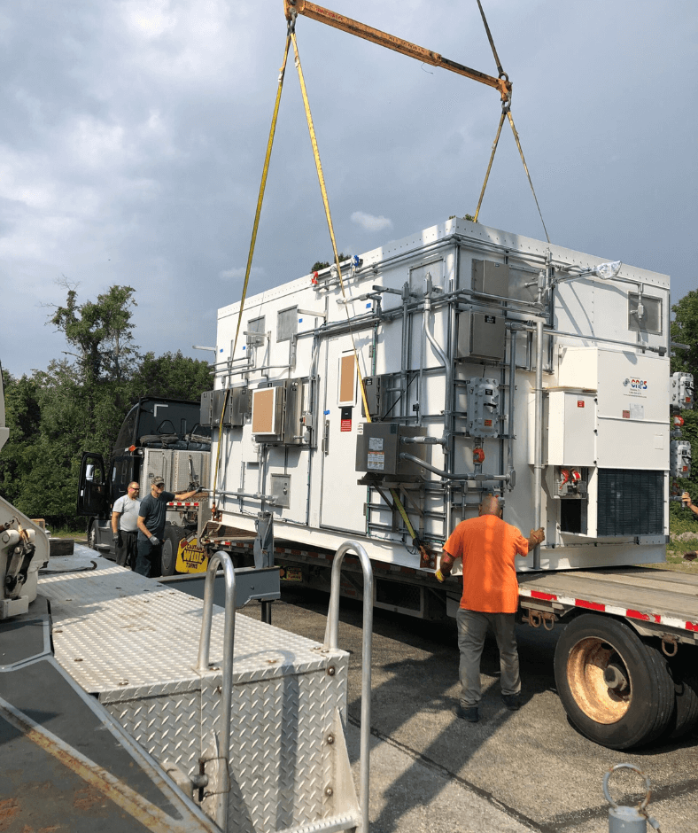
5. Improper Shelter HVAC Systems
Analyzer shelters require stable environmental conditions to support reliable measurements.
Common causes: Undersized air conditioning systems, lack of heating capability, and large temperature fluctuations.
How to identify it: Calibration issues that correlate with outdoor temperature changes, analyzer alarms that appear during summer heat or winter cold, and visible condensation inside the shelter are all signs that environmental conditions are outside acceptable limits.
How to prevent it: Install HVAC systems designed for year-round operation, maintain stable shelter temperatures, and monitor environmental conditions routinely.
Maintaining shelter temperatures between approximately 72°F and 78°F can help improve analyzer stability and reduce calibration issues.
 |  |
6. Dirty Gas Coolers
Gas coolers are often overlooked until performance begins to suffer.
Common causes: Infrequent inspections, lack of preventative maintenance, and dirt and corrosion buildup.
How to identify it: Rising sample temperatures, increased moisture in the sample downstream of the cooler, and declining analyzer stability can all indicate a cooler that’s no longer performing adequately. Because cooler degradation is gradual, the connection to downstream analyzer problems isn’t always obvious.
How to prevent it: Conduct regular visual inspections, establish cleaning intervals, and inspect for corrosion and performance degradation.

7. Damaged Umbilicals
Umbilicals are critical to maintaining sample integrity between the probe and analyzer. Once moisture enters an umbilical, damage can accelerate rapidly, particularly during freeze-thaw cycles.
Common causes: Water intrusion, damaged insulation, poor sealing practices, and aging components.
How to identify it: Unexplained moisture in the sample system, calibration instability that can’t be traced to the analyzer or conditioning system, and visible physical damage to the umbilical jacket are all indicators. Problems often surface — or worsen — after the first hard freeze of the season.
How to prevent it: Inspect umbilicals regularly, verify heater operation, seal connection points, and address leaks before winter weather arrives.

8. Neglected Probe Tubes and Sample Ports
Probe tubes and sample ports often receive attention only after a failure occurs. Routine inspections can prevent complete sample flow loss and unexpected outages.
Common causes: Lack of preventative maintenance, particulate accumulation, corrosion, and mechanical damage.
How to identify it: Declining sample flow, increased pressure drop across the probe, and unexplained analyzer instability can all indicate that probe tubes or sample ports are partially restricted. Complete flow loss is typically the point at which neglected probes are first discovered — at which point an outage is already underway.
How to prevent it: Inspect every 12–24 months, remove buildup before restrictions develop, and replace damaged components proactively.
 |  |  |  |
9. Winter-Related Sample System Failures
Cold weather can expose weaknesses throughout a CEMS installation.
Common problems: Flange leaks, frozen sample lines, calibration instability, and restricted flow paths.
How to identify it: Calibration instability that appears during cold snaps, reduced or lost sample flow, flange leaks that develop or worsen in cold weather, and frozen sample lines are the most common winter failure patterns. Systems that performed adequately through fall may fail quickly once sustained cold arrives.
How to prevent it: Verify insulation integrity, maintain adequate heat tracing, and inspect vulnerable areas before winter arrives.
Preparing for seasonal changes is often far less expensive than responding to winter-related failures.
 |  |  |
10. Installation Errors
Even new systems can experience reliability issues when installation details are overlooked.
Common causes: Incorrect flange bolt patterns, poor alignment, and improper component placement.
How to identify it: Persistent flow problems, unexplained leaks at flanges or connections, and calibration issues that begin at startup and don’t resolve with standard troubleshooting are often indicators of installation errors. Systems with these characteristics frequently benefit from an installation review before further component-level troubleshooting.
How to prevent it: Verify flange drawings before installation, follow installation QA procedures, and perform thorough post-installation inspections.
A few extra minutes during installation can prevent hours of future troubleshooting.

11. Disorganized CEMS Racks
Poor organization can make troubleshooting and maintenance significantly more difficult.
Common causes: Unlabeled components, inconsistent tubing routing, poor documentation, and difficult equipment access.
How to identify it: Technicians spending excessive time tracing lines before performing routine maintenance, unlabeled or inconsistently labeled components, tubing runs that don’t match current system diagrams, and difficulty locating isolation points or service connections are all signs of a rack that needs organizational attention.
How to prevent it: Label components clearly, maintain current documentation, organize tubing and wiring, and conduct periodic system reviews.
A well-organized rack not only looks better — it reduces troubleshooting time and improves long-term maintainability.
 |  |
What Most CEMS Failures Have in Common
While the issues above vary, most share the same underlying causes, including deferred maintenance, inadequate inspection frequency, environmental exposure, improper equipment selection, and small issues that go unaddressed until they become outages.
The most effective CEMS programs share three traits: scheduled inspections tied to operational cycles, documentation that tracks component condition over time, and a clear escalation path when field technicians identify emerging issues.
CEMS Field Services from Alliance Technical Group
Alliance Technical Group provides CEMS field services to industrial and utility facilities across North America. Our technicians perform preventative maintenance programs, system inspections and assessments, analyzer troubleshooting and repair, umbilical replacement, calibration and QA/QC support, emergency field service response, and CEMS upgrades and retrofits.
Facilities working with Alliance typically use our field services to address recurring reliability issues, prepare for regulatory audits, evaluate aging equipment, or establish a structured maintenance program where none previously existed.
If your facility is experiencing unexplained downtime, calibration drift, or compliance data gaps, a CEMS system assessment is a practical starting point. Alliance technicians can evaluate your current installation, identify emerging issues, and recommend a maintenance approach based on your process conditions and regulatory requirements.